Last updated: 10 May 2022
This project will show you how to create a very easy but realistic flame effect using Arduino and some LEDs.
There are other examples around the web but none of them really give the impression of a real fire; they are more random "flicker" routines which produce the impression of cheap christmas tree lights short-circuiting.
You can use the flame effect tutorial as an introduction to programming Arduino/AVR (or even an introduction to programming in general) as the code only requires extremely basic coding skills.
In fact, the flame effect example is a very good project for children (or grown-up children :) using Arduino for the first time). All the instructions have an explanation which assumes you have never seen an Arduino in your life.
As the tutorial steps through the most rudimentary commands, you can consider it a "hello world" project. It's more fun (and useful, assuming you have a genuine need for a fire effect somewhere around your house) than the ubiquitous blink lesson. If you've never tried a blink example, have run one and were immediately bored with it or, if you're very lucky, have no idea what the blink example is, then consider this page your Arduino "101".
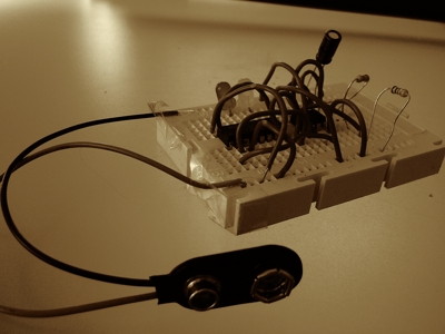
The first time I built this flame effect project on Arduino was, by popular request, for my children's nativity scene one Christmas. In fact this was the reason I bought and programmed my first Arduino. Several Christmases before then I had achieved a similar, but not so realistic, flame effect with a 4026 counter chip, NE555 timer chip, a capacitor and a couple of resistors on a bread board (plus some sticky tape)I got the wiring diagram from some page on the web which I can't find now despite my best search queries. I'm guessing it no longer exists, but if anyone knows of the URL, just send it to me in the comments and I will happily add a reference..
Contents
Stuff you'll need
(includes paid links)
- Arduino board (any model + USB connector)
- LEDs (red X 2, yellow X 2)
- resistors (330Ω x 4)
- jumper wires (male-to-male X 4)
- solderless breadboard
Steps
Wiring
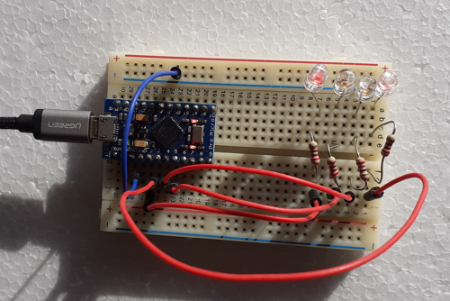
Wire up your Arduino as in the following breadboard diagram. This shows 4 LEDs connected to Arduino pins 2, 3, 4 and 5. Each LED is connected to the digital output pins via a 330Ω resistor and connected to earth (GND). Of course you can use less or more LEDs but obviously you'll need a minimum of one red LED and one yellow LED to achieve a semblance of flames.
On Arduino Uno (the most common set-up):

On Arduino micro pro (a more compact set-up):

Here's the schematic (for both set-ups):

Programme the Arduino
Create a new sketchFile > New in the Arduino IDE.
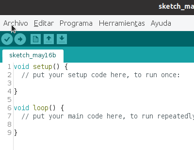
Two methods have been created automatically for us: setup()
The instructions in setup()
will be executed once when the Arduino is powered up.
and loop()
The instructions
in loop() will run repeatedly until
you unplug the Arduino from its power source (USB cable, battery).
.
Before we write the logic for these functions, create a
global variable r which we'll
use to assign a random number whenever we need (and, as
you'll see, we will need it):
long r;
Add the set-up code. This tells pins 2, 3, 4 and 5 that they are OUTPUTs; we will be sending an electrical current to them.
void setup(){
  pinMode(2, OUTPUT);
  pinMode(3, OUTPUT);
  pinMode(4, OUTPUT);
  pinMode(5, OUTPUT);
}
Now we create a function that will light up or turn off
one of our LEDs (pin x).
The first line generates a random number
between 0 and 100.
If that number is less than 90,
the second line of the function will do
digitalWrite(x, true) and the
LED connected to pin x will light
up; otherwise
it will do digitalWrite(x, false)
and the LED connected to pin x will
turn off.
In other words each LED will be lit up 90%
of the time. This is the key to getting a
realistic flame effect!
void flicker(int x){
  r = random(100L);
  digitalWrite(x, r < 90);
}
Now all we have to do is add the logic to the
loop() function, which
just calls our flicker()
function for pins 2, 3, 4 and 5 and then pauses
for a tenth of a second before repeating.
void loop(){
  flicker(2);
  flicker(3);
  flicker(4);
  flicker(5);
  delay(100);
}
The complete code looks like this:
long r;

void setup(){
  pinMode(2, OUTPUT);
  pinMode(3, OUTPUT);
  pinMode(4, OUTPUT);
  pinMode(5, OUTPUT);
}

void flicker(int x){
  r = random(100L);
  digitalWrite(x, r < 90);
}

void loop(){
  flicker(2);
  flicker(3);
  flicker(4);
  flicker(5);
  delay(100);
}
Upload the code to your Arduino
Connect your Arduino to the computer using the USB cable and
make sure the correct board and USB port are selected in
the tools menu.
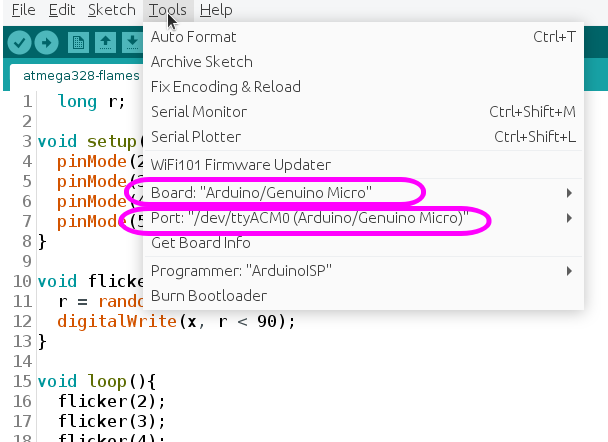
Now uploadSketch > Uploador Ctrl + U your code to the chip.
You should see something like this in the console and status bar:
Done uploading
Sketch uses 4626 bytes (16%) of program storage space. Maximum is 28672 bytes.
Global variables use 157 bytes (6%) of dynamic memory, leaving 2403 bytes for local variables. Maximum is 2560 bytes.
And even more importantly you should see your LEDs twinkling as if they were flames :)
If you see a load of red text in the console that includes
the following error messages,
you have probably selected the wrong board. In this case, check
the board specified in the Tools menu.
An error occurred while uploading the sketch
Arduino: 1.8.5 (Linux), Board: "Arduino/Genuino Mega or Mega 2560, ATmega2560 (Mega 2560)"
Archiving built core (caching) in: /tmp/arduino_cache_752042/core/core_arduino_avr_mega_cpu_atmega2560_db99e0ab099901ba14487a14637cc883.a
Sketch uses 1908 bytes (0%) of program storage space. Maximum is 253952 bytes.
Global variables use 17 bytes (0%) of dynamic memory, leaving 8175 bytes for local variables. Maximum is 8192 bytes.
avrdude: stk500v2_ReceiveMessage(): timeout
avrdude: stk500v2_ReceiveMessage(): timeout
avrdude: stk500v2_ReceiveMessage(): timeout
avrdude: stk500v2_ReceiveMessage(): timeout
avrdude: stk500v2_ReceiveMessage(): timeout
avrdude: stk500v2_ReceiveMessage(): timeout
avrdude: stk500v2_getsync(): timeout communicating with programmer
An error occurred while uploading the sketch
If you see a load of red text in the console that includes
the following error messages,
you have probably selected the wrong port. In this case, check
the port specified in the Tools menu.
avrdude: error: programmer did not respond to command: exit bootloader
Arduino: 1.8.5 (Linux), Board: "Arduino/Genuino Micro"
Sketch uses 4626 bytes (16%) of program storage space. Maximum is 28672 bytes.
Global variables use 157 bytes (6%) of dynamic memory, leaving 2403 bytes for local variables. Maximum is 2560 bytes.
avrdude: butterfly_recv(): programmer is not responding
avrdude: butterfly_recv(): programmer is not responding
avrdude: butterfly_recv(): programmer is not responding
avrdude: butterfly_recv(): programmer is not responding
avrdude: butterfly_recv(): programmer is not responding
Found programmer: Id = ""; type = �
Software Version = �.�; Hardware Version = �.
avrdude: butterfly_recv(): programmer is not responding
avrdude: butterfly_recv(): programmer is not responding
avrdude: error: buffered memory access not supported. Maybe it isn't
a butterfly/AVR109 but a AVR910 device?
avrdude: initialization failed, rc=-1
Double check connections and try again, or use -F to override
this check.
avrdude: butterfly_recv(): programmer is not responding
avrdude: error: programmer did not respond to command: leave prog mode
avrdude: butterfly_recv(): programmer is not responding
avrdude: error: programmer did not respond to command: exit bootloader
avrdude: error: programmer did not respond to command: exit bootloader
Check Out the Results
Your LEDs should be flickering like a real fire. I really wish I'd taken the next photo in the dark :(
Then just cover the LEDs and board with twigs or straw etc and place it in your dioramayour miniature scene or model with the USB cable plugged into a wall adapter or battery. Here's my (albeit slightly blasphemous) nativity scene. Thankfully, I did take this photo in the dark:
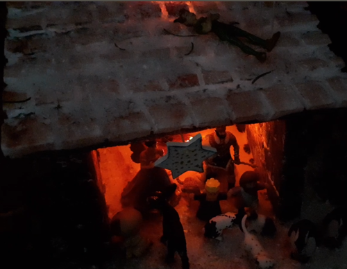
Lights (I mean flames), camera, action!!!
And if you don't want to tie up your Arduino in your children's nativity scene all over christmas, this post shows you how to port this exact project onto a $1 ATtiny85 chip!