Last updated: 16 April 2022
Port manipulation lets you read, write and set the read/write status of Arduino (or ATMega) pins 60 times faster and by using less memory.
Most of the time port manipulation would be over-kill (especially for very basic projects such as the flame effect example) but sometimes, as we'll see, it's very useful for optimisation and in some cases even essential!
Further down this page you'll find tables which show the mapping between the Arduino or ATMega328 pins to their port manipulation equivalent. You can select combinations of multiple pins in the first table and the resulting port manipulation one-liner is displayed in the second table.
So if you are already familiar with how port manipulation works and just want the tables as an easy reference, you can skip the explanation and jump straight to the mapping tables and then create a bookmark in your browser so you will always have convenient access while you are working on your projects.
Contents
- How Port Manipulation Works
-
ATMega328 pin/port mapping table
- Show operations as:
- port manipulation
- Simultaneous operations on multiple pins
- Notes on the table (some for advanced developers)
How Port Manipulation Works
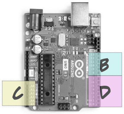
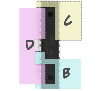
The pins on the ATMega328 (the chip that Arduino uses) are grouped physically into blocks ("ports"):
D, B and C.
Each port contains up to 8 pins.


When your code looks like it communicates with any single pin it is actually communicating with all the pins in its entire port using a byte of information!
1 byte is 8 bits, so enough information for up to 8 pins. Ports D and B have 8 pins; while port C only has 7 pins.
When, for example, you write
digitalWrite(9, HIGH);
it looks like you are just saying
"pin 9 - go HIGH" (ie. send current through pin 9, to light an LED, for example)
You are doing this of course; but you are not just setting pin 9 to high! Because of the way the ATMega chip works physically, you are actually talking to all the pins in the block.
The underlying code is doing this:
"pin 8 - do nothing"
"pin 9 - go HIGH"
"pin 10 - do nothing"
"pin 12 - do nothing"
"pin 11 - do nothing"
"pin 13 - do nothing"
"XTAL1 pin - do nothing"
"XTAL2 pin - do nothing"
In addition, the digitalWrite() function needs to perform
extra background logic.
BUT... it's possible to combine all those commands into one single command and skip the additional logic, AKA "port manipulation".
But why would you bother doing that when you have
perfectly good intuitive commands like digitalWrite(),
digitalRead() and pinMode()?
Two reasons:
- to save memory space
- speed
Both of these advantages increase when you talk to multiple pins at the same time. Port manipulation lets you interact with all the pins in a port simultaneously with a single instruction.
For example, instead of writing (on Arduino):
    digitalWrite(2, HIGH);
    digitalWrite(4, HIGH);
    digitalWrite(6, HIGH);
    digitalWrite(7, HIGH);
...you can just write:
PORTD |= 212;
So how does that work???
Port manipulation syntax
Before we look at interacting simultaneously, let's look at a simpler example.
PORTB |= 4;is the same as
digitalWrite(10, HIGH);
PORTB |= 4; might look strange (especially if you
aren't familiar with bitwise operations) but it's really a very normal
piece of C code.
It's
simply a variable (PORTB), followed by
an operator (|=), followed by a
value (4).
Let's break it down:
The variable
In this case the variable is a special built-in variable used for port manipulation which represents a "register" (a place in memory used by the microcontroller to manage state). Register variables are named according to the following prefix/suffix convention:
the instruction followed by the port you're talking to
The table below shows the 3 instruction parts with meanings and their high-level equivalents (the x needs to be substituted by the port you are interested in):
| Port manipulation instruction | Meaning | Equivalent high-level function |
|---|---|---|
| DDRx | set the data direction of one or more pins (INPUT or OUTPUT) | pinMode() |
| PINx | read the state of one or more pins | digitalRead() |
| PORTx | set the state of one or more pins (HIGH or LOW) | digitalWrite() |
In our basic example PORT is a prefix meaning
digitalWrite() and the B suffix
indicates port B.
So PORTB... is saying "let's write (HIGH or LOW) to
one or more pins on port B".
The operator
The operator is a "bitwise" operator (because we are manipulating individual bits).
You only need to know three, but their effects are very different depending on how you combine them with the possible values:
|=bitwise OR assignment&=bitwise AND assignment&bitwise AND test
Here's how to use them. All of the examples operate on
Arduino pin 10 (remember that the 4 in each
example is binary 100 and Arduino pin 10
is port B bit 2 - third position from the right):
| High-level function equivalent | Syntax | Example | Explanation |
|---|---|---|---|
pinMode(pin, OUTPUT) |
DDRx |= value | DDRB |= 4 |
The example sets Arduino pin 10 as an output. |
pinMode(pin, INPUT) |
DDRx &= flipped value | DDRB &= ~4 |
The ~ sign is important! This forces our selected bits
to zero while all other bits remain unchanged.
The example sets Arduino pin 10 as an input. |
if (digitalRead(pin) == HIGH) .... |
(PINx & value) | if (PINB & 4) .... |
The example tests whether Arduino pin 10 is HIGH. |
if (digitalRead(pin) == LOW) .... |
(!PINx & value) | if (!PINB & 4) .... |
The example tests whether Arduino pin 10 is LOW. |
digitalWrite(pin, HIGH) |
PORTx |= value | PORTB |= 4 |
The example sets Arduino pin 10 to HIGH. |
digitalWrite(pin, LOW) |
PORTx &= flipped value | PORTB &= ~4 |
The ~ sign is important! This forces our selected bits
to zero while all other bits remain unchanged.
The example sets Arduino pin 10 to LOW. |
The value
The value is a number which indicates which pin or combination of pins we are talking to.
Each port is represented by a byte (8 bits); and each pin in the port is represented by a single bit. So this exposes up to 8 pins for port manipulation. In the case of port B there are 8 pins which map to the following bit slots:
| Arduino pin | port B position |
|---|---|
| 8 | 0 |
| 9 | 1 |
| 10 | 2 |
| 11 | 3 |
| 12 | 4 |
| 13 | 5 |
| 13 | 5 |
| XTAL1 | 6 |
| XTAL2 | 7 |
Using the PORTx variable, if you set a bit
to 1 you set its corresponding pin
to HIGH; if you set a bit
to 0, its corresponding
pin will go LOW. In fact, the
variables HIGH and
LOW are simply constants that
mean 1 and
0 repspectively.
digitalWrite(10, HIGH), for example, really means
digitalWrite(10, 1).
|= is the C++ bitwise OR assignment operator.
It's a bit like = but instead of setting the value
of the whole variable, it changes individual bits of the variable to
1. Because each of the bits represents a pin,
|= will set our selected pins
to HIGH.
But which pins???
In this example we are only affecting one pin, but which one?
The previous table shows that Arduino pin 10 is port B position 2.
So what does the 4 in PORTB |= 4 mean?
4 in binary is 100, so
we are manipulating the 3rd bit from the right, which corresponds
to Arduino pin 10.
| Arduino pin | XTAL2 | XTAL1 | 13 | 12 | 11 | 10 | 9 | 8 |
|---|---|---|---|---|---|---|---|---|
| Port B position | 7 | 6 | 5 | 4 | 3 | 2 | 1 | 0 |
| value | 128 | 64 | 32 | 16 | 8 | 4 | 2 | 1 |
Now let's look at our first example that interacted with
several pins simultaneously: PORTD |= 212;.
The value 212 represents the bits
of PORTD that we want to set to
1.
In binary 212 looks like this: 11010100.
The digits that appear as 1s are the affected bits.
So, counting from right to left and bearing in mind that the first position is
named zero, so we are setting pins 2, 4, 6 and 7.
Note that in port D there are 8 pins and serendipitously all the Arduino pin numbers are the same as the port positions (the ATMega pin numbers, which are all different from the Arduino numbering, do not coincide like this).
| Arduino pin | 7 | 6 | 5 | 4 | 3 | 2 | 1 | 0 |
|---|---|---|---|---|---|---|---|---|
| Port D bit position | 7 | 6 | 5 | 4 | 3 | 2 | 1 | 0 |
| value | 128 | 64 | 32 | 16 | 8 | 4 | 2 | 1 |
Which is how
PORTD |= 212;
is the same as (on Arduino):
    digitalWrite(2, HIGH);
    digitalWrite(4, HIGH);
    digitalWrite(6, HIGH);
    digitalWrite(7, HIGH);
...but a lot faster :)
All the other bits (in this case 0, 1, 3 and 5) remain unchanged.
The following table shows mapping between Atmega328 pinout, Arduino UNO pinout,
ports and Atmega328 register bits for port manipulation. For each pin
it shows the port manipulation equivalent for pinMode(),
digitalRead() and digitalWrite()
operations. You can use the show operations as options to display
values as decimal, hex or binary. Note that these
are just different ways of writing the same number. Sometimes I think
that binary is the most intuitive as a binary number serves
(by definition) as a visual representation of the bits you
are manipulating.
To calculate simultaneous operations on multiple pins, click the checkbox in the combine column for each pin you are interested in. The combined port manipulation command will appear magically in the Simultaneous operations on multiple pins table below :)
ATMega328 pin/port mapping table
Show operations as:
port manipulation
| Atmega 328 |
Arduino UNO |
pin also used for |
port | register bit |
pinMode (OUTPUT) |
pinMode (INPUT) |
digitalRead(x, HIGH) | digitalRead(x, LOW) | digitalWrite(HIGH) | digitalWrite(LOW) | combine |
|---|
Simultaneous operations on multiple pins
| port | pinMode(OUTPUT) | pinMode(INPUT) | digitalRead(x, HIGH) | digitalRead(x, LOW) | digitalWrite(HIGH) | digitalWrite(LOW) |
|---|
Notes on the table (some for advanced developers)
-
Display values in different bases
Use the Show operations as: radio buttons to show values as decimal, hexadecimal or binary. Note that this does not change the values in any way - they are just formatted as a different base. For example,
16,0x10andB10000are simply different ways of writing the same number. -
Combining operations
You can select operations on multiple pins by using the checkboxes in the Combine column. The resulting operation is shown for each port in the Simultaneous operations on multiple pins table.
-
Setting pull-up resistors with port manipulation
Bearing in mind that
pinMode(x, INPUT_PULLUP)doespinMode(x, INPUT)followed bydigitalWrite(x, HIGH), the following 2 code examples achieve the same result:pinMode(4, INPUT_PULLUP);
DDRD &= ~0x10;   // input mode
PORTD |= 0x10;   // set high
-
ATMega pin numbering
ATMega 328/P pin numbering refers to 28-PDIP format.
-
Which pins are listed in the table?
The table shows all the pins which are available for port manipulation.
So far as I can tell (from testing and the ATMEGA 328/P datasheet), these are all the pins that can be used for digital read and write; and all have an internal pull-up resistor.
-
Why is RESET greyed out?
It's not impossible to use the
RESETpin for digital IO (and hence port manipulation) but you probably won't want to. TheRESETpin is an input which always reads high during normal runtime (current is passing through it via its internal pull-up resistor). When it goes LOW, whatever code is currently executing terminates and restarts. It's designed to go low by being connected to ground by a physical button. You can also trigger a reset from your code but you wouldn't do this by manipulating the reset pin directly. -
Why are the XTAL pins greyed out?
The XTAL (crystal) pins are intended to connect to an external crystal oscillator which serves as the clock to ensure constant speed of the chip's processes.
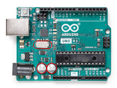
They are not accessible on the Arduino because they do not exist along the female headers. They are physically hard-wired to the board and connect to the 16MHz crystal clock via two capacitors (clearly visible on the board).

Crystal oscillator and capacitors on an Arduino UNO Both XTAL pins are accessible on a stand-alone ATMega chip but probably not useful.
On the ATMega328 chip the XTAL pins are just legs (9, 10) like all the other pins. But this assumes you are using the ATMega's internal 8MHz clock. To do this you need to upload a specific bootloader (code that sets up the chip before your programme code starts running) to tell the chip to use its internal clock. There are several ways to do this - including using the Arduino IDE.
Pros of ditching the external clock on a stand-alone project
- less power (important if you intend your device to sit in the middle of a remote olive grove)
- less wiring/soldering (important if... well, I won't even explain why that's important)
Cons of ditching the external clock on a stand-alone project
- less speed (the internal AtMega328 clock runs at 8MHz compared the external 16MHz oscillator supplied with the Arduino)
- less precision (the ATMega328 internal clock is relatively erratic - acceptable for many projects; but completely useless if your logic depends on microsecond-level timing)
-
also used for column
Special functions such as communication with other chips or devices happens on dedicated pins. If your programme uses one of these functions, then you will have to avoid digital IO on the associated pins to prevent conflicts. The also used for column highlights the functions (I'm guessing) you are most likely to use.
-
TX, RX
Avoid these pins if you are planning on using USART serial communications. Note that serial communication includes the USB connection! Meaning, if you are using
Serial.println(···)to output to a console, you should stay clear of these two pins. Even if your finished programme doesn't do any serial communication, your debugging messages will cause issues with the behaviour of these two pins. -
MOSI, MISO, SCK
Avoid these if you are planning on using SPI serial communications. ATMega pin 16 (arduino pin 10) also carries the slave enable/disable signal (SS); so it won't be available if your SPI code requires that.
-
SCL, SDA
Avoid these if you are planning on using I2C communications.
-